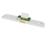
The PCBS series is a family of integrated automotive current sensing modules that combine a precision low-resistance shunt, an NTC temperature sensor, and a signal conditioning PCBA in a single bolt-mounted assembly designed for direct integration into battery disconnect units (BDU) and power distribution units (PDU) in electric and hybrid vehicle powertrains. Unlike bare shunt resistors that require external signal conditioning circuitry and temperature compensation to be designed into the host system, each PCBS module delivers a conditioned, temperature-compensated current signal directly to the user’s signal processing module through a standardised Molex connector, substantially reducing the design and calibration burden on the system integrator. The module is described as a PCB+SHUNT assembly and is customisable to specific technical requirements.
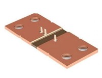
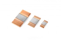
The shunt element in each PCBS module operates at the micro-ohm level — 25 μΩ, 50 μΩ, or 100 μΩ — to accommodate bidirectional continuous currents from ±350 A to ±1000 A within the rated operating range, and peak currents significantly beyond this on a short-term basis: up to ±1000 A for 5 seconds on the 100 μΩ model and up to ±3000 A for 5 seconds on the 25 μΩ model. The shunt TCR is ≤±100 ppm/°C, and the integrated NTC thermistor — rated at 10 kΩ ±1% with a B-value of 3434 K or 3435 K depending on model — allows the host system to read shunt temperature continuously and apply real-time temperature compensation to the measured resistance using the quadratic correction formula Rₜ = R₀ × Rᶜᵒᵐᵖ(T), where Rᶜᵒᵐᵖ is computed from the per-unit polynomial coefficients A, B, and C encoded in the data matrix label on each module.
Each PCBS unit is individually characterised at the factory, and the measured initial resistance R₀ at 25°C ±2°C, accurate to ±0.2%, together with the three temperature compensation coefficients, is encoded in a data matrix label applied to the PCB cover. This per-unit calibration data allows the host BMS or signal processor to correct for both the absolute resistance value at reference temperature and its temperature-dependent drift, achieving current measurement accuracy substantially better than the ±5% shunt tolerance alone would suggest. The connector pinout is defined for two configurations: a 4-pin Molex 5023520400 connector carrying the current signal positive and negative sense lines and two NTC temperature sensor pins for the single-channel models, and a 9-pin Molex 5023520900 connector with multiple current signal group pairs, a common-mode ground, and NTC pins for the dual-channel models. Installation requires copper bar connections of the recommended width and thickness, overlapping the shunt by at least 20 mm and clamped without flat washers between the bar and shunt surface to preserve the integrity of the electrical contact. Qualification testing is performed to VW 80000-2021 and relevant GB/T Chinese national standards, covering insulation resistance, dielectric strength, temperature drift, high and low temperature ageing, thermal shock, damp heat, temperature cycle durability, salt spray, free fall, vibration, and mechanical shock.