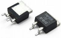
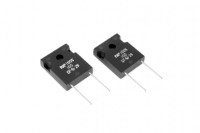
The TNP20 series from RARA Electronics is a high power wideband resistor supplied in a TO263 (D2PAK) surface mount package. It is rated at 35W when the flange is held at a temperature between -55°C and +25°C, and at 2W in free-air operation without a heatsink. The part is AEC-Q200 grade, RoHS 2 compliant and made with UL94 V-0 certified material, with a maximum operating temperature of 175°C. It supports both reflow and wave soldering.
The series is offered in three models, TNP-20D, TNP-20E and TNP-20F. The resistive element is thick film (RuO) over an alumina substrate, with a thin film (NiCr) option for 10Ω to 51kΩ. Resistance covers 0.01Ω to 1MΩ, using a modified E24 series of values, and the resistance value and tolerance can also be customised beyond E24. Tolerance is ±1% or ±5%, and TCR options of 50, 100, 150 and 250ppm/°C are available, with TCR and tolerance determined by the resistance value. For low resistance values the TCR depends on the copper terminals, and the datasheet gives 300ppm/°C at 0.02Ω, 200ppm/°C at 0.05Ω, 140ppm/°C at 0.1Ω and 80ppm/°C at 0.2Ω.
The datasheet states a maximum operating voltage equal to the smaller of 500V or √(P×R), with a maximum input current of 20A. In some high and low ohmic cases the full rated power cannot be applied because of these limits, so operation should stay under 500V above 7kΩ and below 20A under 0.1Ω. The flange is insulated from the internal resistive elements, with insulation resistance of at least 1,000MΩ and an insulation voltage of at least 2,000VAC for one minute between terminal and flange. Typical thermal resistance between the resistive material and the flange is 3.3°C/W, and the part weighs 1.5g.
As the wideband name suggests, the TNP series is designed to keep a stable impedance across a wide frequency range. The datasheet gives a typical inductance of 8.38nH between terminals and a typical capacitance of 1.44pF between terminal and flange, and it includes frequency characteristic curves plotted from 100kHz to 10GHz. The datasheet also provides derating, temperature rise and pulse energy durability curves. Reliability data is reported to AEC-Q200 for high temperature exposure, temperature cycling, moisture resistance, high temperature operating life, terminal strength and vibration, and a continuous-pulse power allowance at a duty of 0.01 is noted as tentative.
Because the part depends on heat transfer through its flange, it should be mounted on a heatsink for operation above 2W. The datasheet lists conditions the product is not designed for, including direct sunlight, outdoor exposure, dusty environments, corrosive gases, strong electrostatic discharge or electromagnetic interference, continuous condensation, radiation and vacuum environments, and mounting methods where the part is isolated from the heat dissipation system or encapsulated in resin. Performance should be verified in the actual equipment, especially with pulsed loads. The series is supplied on tape reel (Z01) or in PVC stick packaging (Z03).